This document compiles 26 common‑operation issues and 24 typical equipment faults of reverse‑osmosis systems. It fully covers core scenarios including daily operation & maintenance, parameter commissioning, fault diagnosis and equipment maintenance for RO systems. It corrects widely‑seen ambiguous descriptions and non‑standard practices in the industry. With field‑oriented practical guidance, it can resolve the vast majority of operational problems of reverse‑osmosis equipment.
Part 1 Common‑Occurring Issues of Reverse‑Osmosis Systems (26 Questions)
1. How to determine the cleaning cycle of a reverse‑osmosis system?
Judgment criteria: Clean the system immediately when the normalized flux or salt rejection drops by 10%~15%, or the operating pressure / inter‑stage differential pressure rises by 10%~15%.
Cleaning frequency: 4 times per year when feed‑water SDI₁₅<3; the frequency is doubled when SDI₁₅≈5. The final cleaning schedule shall be subject to actual on‑site working conditions.
2. What is SDI and its core function?
SDI stands for Silt Density Index, a key parameter for evaluating colloidal fouling of RO/NF feed‑water, tested in accordance with ASTM D4189‑82.
Operating requirement: RO feed‑water SDI₁₅ ≤ 5; surface water shall be tested 2‑3 times a day.
SDI reduction methods: Multimedia filtration, ultrafiltration, microfiltration. Appropriate dosage of polyelectrolyte in pretreatment can improve filtration performance.
3. Reverse‑osmosis or ion‑exchange process for feed‑water treatment?
Make the decision mainly based on feed‑water salinity:
Reverse‑osmosis delivers better cost‑efficiency at high salinity; ion‑exchange is more economical for low‑salinity water.
Nowadays, the industry generally prefers the combined process of RO + ion‑exchange / advanced desalination, balancing stable performance and low operating cost.
4. What is the service life of reverse‑osmosis membrane elements?
Membrane lifespan depends on membrane stability, influent water quality, pretreatment performance, cleaning frequency and O&M quality. Under normal operating conditions, the economical service life can exceed 5 years.
5. Core differences between reverse‑osmosis and nanofiltration
Nanofiltration (NF) is a low‑pressure membrane technology between ultrafiltration and reverse‑osmosis.
RO can intercept extremely tiny solutes (particle size <0.0001 μm) with ultra‑high salt rejection.
NF retains solutes around 0.001 μm, mainly for hardness removal, also known as "softening membrane". It features low operating pressure and low energy consumption, suitable for pretreatment of well water and surface water with moderate water‑purity requirements.
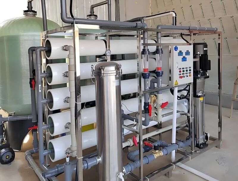
6. Separation capacity differences among various membrane technologies
Reverse‑Osmosis: Precision filtration, retains inorganic salts and organics with molecular weight>100; salt‑rejection rate 95%~99%; operating pressure 7‑69 bar.
Nanofiltration: Retains 1 nm impurities and organics with molecular weight of 200‑400; monovalent‑salt removal 20%~80%; divalent‑salt removal 90%~98%.
Ultrafiltration: Retains macromolecules, colloids and bacteria, while allowing small salt molecules to pass through; molecular‑weight cutoff: 1 000‑100 000.
Microfiltration: Retains suspended solids and bacteria of 0.1‑1 μm, permeable to salts and macromolecules.
7. How to obtain membrane cleaning chemicals and cleaning services
You may purchase dedicated membrane cleaning agents directly from water‑treatment equipment manufacturers, or entrust manufacturers to provide professional cleaning services. If on‑site operation & maintenance capability is available, perform self‑cleaning in strict accordance with membrane manufacturer’s specifications.
8. Maximum allowable silica concentration in RO feed‑water
The limit is affected by water temperature, pH and antiscalants.
Without antiscalant: silica limit at concentrate side = 100 ppm.
With dedicated antiscalant: the upper limit can be raised to 240 ppm.
Final parameters shall follow the antiscalant supplier’s documentation.
9. Hazards of chromium to RO membranes and countermeasures
Hexavalent chromium can catalyze chlorine‑oxidation reactions and cause irreversible damage to membrane sheets. High‑valent metal ions bring even stronger destructive effects.
Solutions: Reduce chromium content in pretreatment, or reduce hexavalent chromium into stable trivalent chromium.
10. Standard pretreatment process for RO systems
Standard workflow: 80 μm coarse filtration → oxidant dosing (sodium hypochlorite) → multimedia filtration / clarifier fine filtration → sodium bisulfite dosing for residual‑chlorine reduction → cartridge filtration before high‑pressure pump.
Targeted pretreatment: Add softening / acid‑dosing plus antiscalant process for high‑hardness feed water; install activated‑carbon filters or select fouling‑resistant membranes for water with high organics and microbial loads.
11. Can reverse‑osmosis remove bacteria and viruses?
RO membranes have extremely dense structure, achieving ≥99.9% removal rate (over 3‑log reduction) for bacteria and viruses.
Note: The membrane itself does not cause secondary contamination. Microbial growth on the permeate side is mainly caused by improper system assembly, maintenance and flushing.
12. Influence of water temperature on permeate flow rate
Permeate output is positively correlated with water temperature: higher temperature yields higher permeate flow.
Properly lower operating pressure at high temperatures and increase pressure at low temperatures to maintain rated water production. Precise regulation can be carried out with reference to the Temperature Correction Factor (TCF).
13. Causes and detection methods of particulate / colloidal fouling
Causes: Silt, colloidal silica, iron corrosion by‑products, residual coagulants (polyaluminum, polyelectrolytes) and precipitates from reactions between anionic and cationic chemicals will lead to membrane fouling.
Fault symptoms: Increased system differential pressure and reduced permeate output.
Detection: Evaluate fouling risk and pretreatment performance via the SDI15 index.
14. Maximum shutdown duration without system flushing
With antiscalant dosed:
Water temperature 20~38 ℃: shutdown ≤ 4 hours
Water temperature <20 ℃: shutdown ≤ 8 hours
Without antiscalant: maximum shutdown time = 1 day
15. Can the RO system be started‑stopped frequently? Startup & shutdown specifications
The system is designed for continuous operation; frequent on‑off cycles are not recommended.
Operation rules: After shutdown, perform low‑pressure flushing with qualified permeate / pretreated water to displace concentrate. Never allow air ingress due to water loss, which may trigger irreversible flux decline.
No biocidal protection is required for shutdown shorter than 24 hours. For longer downtime, implement periodic flushing or add preservation solution.
16. Installation direction of membrane element brine seal
Install the brine seal at the feed end of the membrane element. The lip opening faces the feed‑water direction. Feed‑water pressure expands the seal to block the bypass gap between membrane element and pressure vessel, preventing cross‑leakage.
17. Silica removal methods in water
Silica exists in two forms:
Colloidal silica: Removed by coagulation‑clarification or RO filtration; ion‑exchange has no effect.
Reactive silica: Cannot be removed by conventional filtration; effectively eliminated only by RO, ion‑exchange or EDI.
18. Effects of pH on salt rejection, permeate yield and membrane service life
RO membranes tolerate pH 2‑11; pH barely impacts the membrane material itself.
However, pH greatly affects the charge state of dissolved ions in water. Higher ionic charge enhances removal efficiency and vice versa, so pH directly determines impurity‑removal performance.
High pH converts CO₂ into interceptable carbonate ions to improve salt rejection, while scaling risk must be tightly controlled.
19. Conversion relationship between feed‑water TDS and conductivity
For ordinary water sources, conductivity / TDS ratio ranges from 1.2 to 1.7.
General engineering‑design values: 1.3 for brackish water, 1.4 for seawater, which can satisfy accurate design requirements.
20. How to judge that RO membranes are fouled
Six typical indicators:
① Permeate flow drops under standard pressure
② Higher operating pressure is required to maintain water output
③ Sharp rise of inter‑stage differential pressure
④ Increased weight of membrane elements
⑤ Abnormal fluctuation of salt‑rejection rate
⑥ Blocked membrane flow channels; water poured from feed side cannot pass through and overflows only from the end face
21. Prevent microbial growth inside new membrane packaging
Inspect the preservation solution of membrane elements every 3 months. Turbidity indicates microbial proliferation.
Treatment: Take out membrane elements, drain them, soak for 1 hour in 1% food‑grade sodium bisulfite solution, refill with fresh preservation liquid and seal for storage.
22. General feed‑water requirements for RO membranes and ion‑exchange resins
Feed‑water must be free of suspended solids, colloids, algae, bacteria, oxidants such as residual chlorine, oil & grease, high‑concentration organics, metal corrosion products and iron‑organic complexes. Otherwise, service life of membranes and resins will be drastically shortened and effluent quality will deteriorate.
23. What contaminants can RO membranes remove
RO can efficiently trap most impurities. Under normal working conditions:
Salt removal ≥99%, organic‑matter removal ≥99%; it can also stably remove colloids, bacteria, viruses and heavy‑metal ions.
24. Selection of membrane‑cleaning chemicals and protocols
Targeted cleaning is critical; improper cleaning may damage membrane elements:
① Inorganic scaling (calcium‑magnesium scale, silica scale): adopt acidic cleaning solution
② Organic, microbial and colloidal fouling: adopt alkaline cleaning solution, supplemented with disinfection if necessary
25. Causes & solutions for lower permeate pH than feed‑water pH
Root cause: RO membranes retain ions but not CO₂. Most HCO₃⁻ and CO₃²⁻ are removed, breaking the aqueous equilibrium. Dissolved CO₂ reacts with water to produce hydrogen ions, lowering permeate pH by 1‑2 units. Higher feed‑water alkalinity brings a larger pH drop.
Solution: Dose NaOH to adjust permeate pH to 7.5‑8.0 for optimal desalination performance.
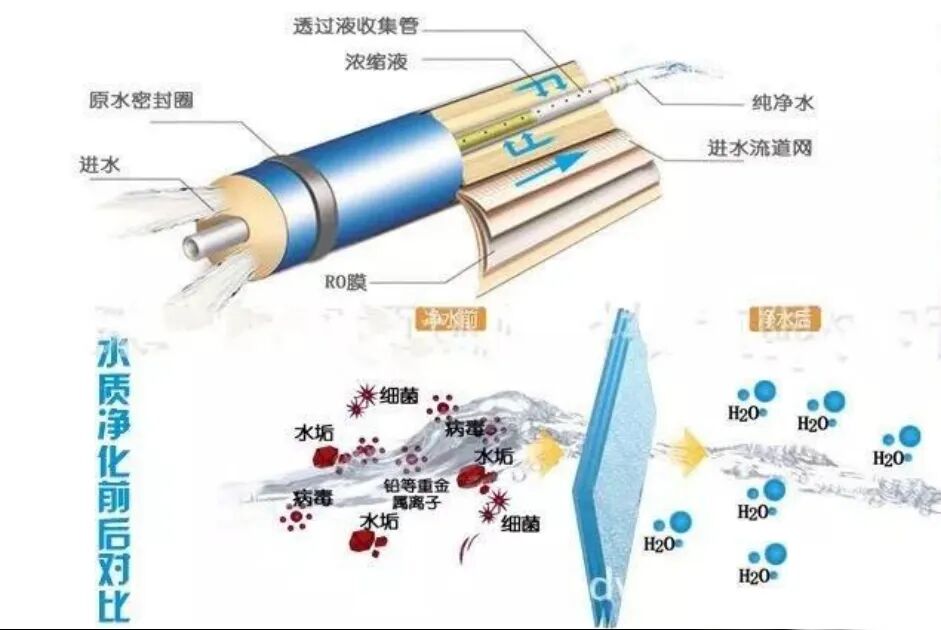
26. How to reduce energy consumption of reverse‑osmosis systems
Adopting dedicated low‑energy membrane elements can effectively cut operating energy consumption.
Note: Low‑energy membranes deliver a slightly lower salt‑rejection rate than standard membranes. Model selection shall be made according to water‑quality requirements.
Part 2 Common‑Occurring Faults of Reverse‑Osmosis Equipment (24 Questions)
1. Causes and hazards of swollen equipment sealing rings
Causes: Vaseline or petroleum‑based grease is used as lubricant during installation.
Hazards: It will not affect system operation, yet make reassembly difficult after disassembly, as the seal cannot be accurately seated into the groove.
Standard practice: Lubricate seals only with clean water or glycerol.
2. Do all membrane elements in the equipment produce the same permeate flow?
No. Along the water‑flow direction, the operating pressure of membrane elements gradually drops, while feed‑water salinity and osmotic pressure keep rising, resulting in progressively decreased permeate output. This is a normal operating phenomenon.
3. Influence of pH on equipment membrane elements
Composite membranes withstand a pH range of 2~11. Under normal working conditions, pH will not damage the membrane material.
However, pH changes the form and electric charge of ions in water, which directly affects salt rejection. Raising feed‑water pH can remove CO₂ and improve water quality, while scaling risk must be strictly controlled.
4. Standard operating procedure for the initial startup of the equipment
Carry out low‑pressure venting and flushing at 0.2~0.4 MPa to fully purge air from pipelines. Discharge all concentrate and permeate.
Rapid pressure rise is strictly forbidden, to prevent air hammer from rupturing the membrane envelope and causing irreversible damage.
Enable the automatic low‑pressure flushing function after commissioning.
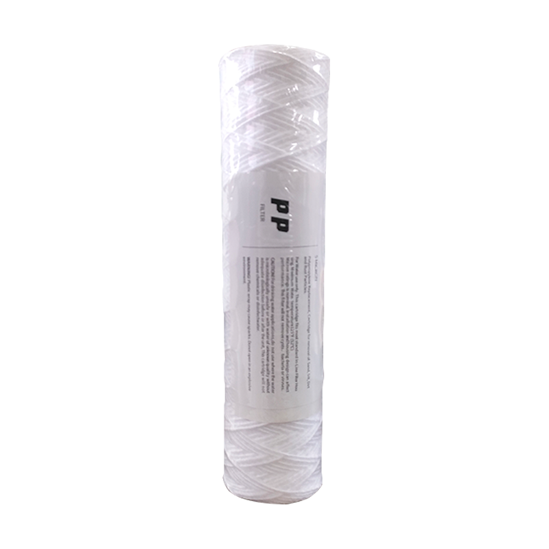
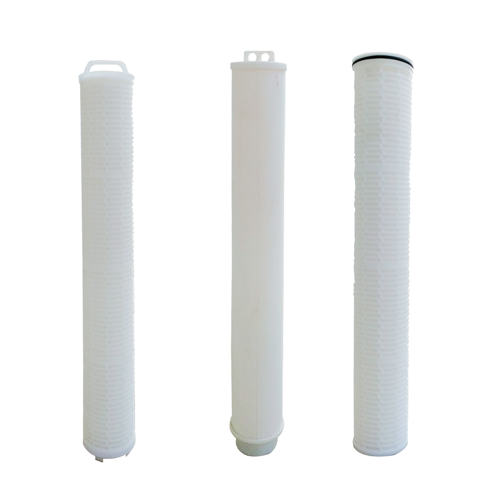
5. Replacement criteria and procedures for cartridge filter elements
Replacement criterion: Differential pressure across the filter exceeds 0.03 MPa.
Operating procedures: Shut down and release pressure → open filter housing → install new filter cartridge → tighten housing → start‑up and trial‑run.
6. Judgment criteria for chemical cleaning and disinfection
Under the same water‑temperature condition, cleaning is required if any of the following occurs:
① Permeate flow drops by 5%‑10% compared with initial state or after last cleaning
② Salt‑rejection rate decreases by 2.5%‑5%
③ Inter‑stage differential pressure rises to 1‑2 times of its initial value
④ Perform cleaning and preservation with protective solution before long‑term shutdown
Cleaning is recommended to be carried out by qualified personnel.
7. Fluoride‑removal performance of RO equipment
Reverse‑osmosis can effectively remove fluoride ions from water and is suitable for fluoride removal of groundwater.
Fluoride‑removal efficiency slightly declines for high‑salinity feed‑water. Compared with other processes, it features simple operation, stable effluent quality and low O&M cost.
8. Basic water‑quality requirements for purified‑water equipment effluent
Raw water shall meet drinking‑water standards.
Total bacterial count of finished water ≤ 100 CFU/mL, Escherichia‑coli‑free.
The equipment shall be cleaned and disinfected periodically, and a terminal sterilization device shall be equipped to avoid secondary pipeline contamination.
9. Key water‑quality characteristics of purified‑water equipment outlet
Fully‑equipped sterilization devices and circulating pipelines (instead of conventional direct‑feed pipelines) effectively inhibit microbial growth and endotoxin over‑limit.
Pipeline flow velocity shall be well‑controlled to prevent bacterial reproduction caused by low flow rate and dead legs.
10. Key points for site selection of water‑softener equipment
① Close to drainage points with unobstructed discharge
② Reserve installation space for other water‑treatment units
③ Leave sufficient area for salt‑adding operation
④ Keep at least 3‑meter distance from boilers to avoid equipment damage by hot‑water backflow
⑤ Ambient temperature: 1 ℃ ~ 49 ℃, prevent freezing in low temperature and malfunction under high temperature
11. Precautions for water‑softener operation
① Keep the inlet valve fully open during normal operation; close it only for maintenance.
② Manual regeneration is allowed when effluent quality fails to meet standards.
③ Fill with brine for preservation before long‑term shutdown.
④ Perform one manual regeneration before system restart.
⑤ Clean the salt tank once a year if the industrial salt contains excessive impurities.
12. Installation standards for ultrapure‑water equipment
① The site shall be flat and clean, close to power supply and water source.
② Keep away from fire sources and heat‑generating units.
③ Outdoor installation is forbidden in northern regions to avoid component damage caused by freezing.
④ Ensure smooth drainage without stagnant‑water dead zones.
⑤ Maintain stable pump operating pressure at 1.0~1.2 MPa under rated working conditions.
13. Troubleshooting for non‑priming booster pumps and high‑pressure pumps
380 V pumps: Check the phase sequence of power supply. Swap any two wires if the pump runs backwards. If rotation direction is correct, open the vent valve for air release and fully fill the pump casing with water.
220 V pumps: Reversal will not occur. Directly vent air and top‑up water inside the pump.
14. Troubleshooting for high‑pressure pump failure to start
Check whether relays and wiring terminals are loose or disconnected. If the water‑shortage indicator is on, it indicates insufficient feed‑water; the water‑cutoff protector triggers self‑locking protection. The pump can start normally after water supply is replenished and pressure reaches the required value.
15. Troubleshooting for abnormal noise of high‑pressure pump
Slight noise is caused by residual air inside the pump casing, which usually disappears automatically within 1‑3 minutes.
For persistent abnormal noise, carry out air venting and water replenishment immediately. Dry‑run operation is strictly prohibited to prevent pump casing wear and damage.
16. Causes and solutions for pipeline burst
Causes: Long‑term failure to replace or clean filter cartridges and membrane elements results in blockage and overpressure inside pipelines.
Solutions: Replace clogged filter cartridges and clean RO membranes. Install an antiscalant dosing system or ion‑exchange equipment for poor‑quality raw water to stabilize water pressure and protect membrane elements.
17. Solutions for continuously declining water output
This problem is mostly caused by membrane fouling due to excessive impurities in groundwater.
Back‑wash pretreatment equipment on a regular basis, replace fine filter cartridges and clean RO membranes. Add an antiscalant pretreatment system for extremely poor raw‑water quality to avoid blockage.
18. Removal of black‑and‑white suspended particles in product water
Causes: Pipeline contamination and microbial proliferation.
Solutions: Circulate caustic‑soda solution through cartridge filters and pipelines for 30 minutes, and adopt a pipeline sterilizer for continuous disinfection to thoroughly remove biofilm and contaminants.
19. Prevention and treatment of membrane damage caused by water hammer
Fault causes: Rapid pressure build‑up with residual air during restart, or air ingress from leaking pipeline joints.
Prevention & solutions: Complete air venting under low pressure (2‑4 bar), then raise pressure gradually after no bubbles are observed. Replace clogged microfiltration cartridges, inspect and fasten all pipe connections. Reduce pressure immediately for maintenance once bubbles are detected during operation.
20. Methods to avoid membrane damage caused by incorrect shutdown
Emergency pressure‑relief shutdown and shutdown flushing with dosed water are prohibited.
Standard shutdown procedure: Stop chemical dosing in advance, reduce system pressure to around 3 bar, and flush for 10 minutes with qualified pretreated water. Shut down only when the concentrate TDS is close to raw‑water TDS.
21. Causes and prevention of microbial contamination
Main causes: Polyamide membranes have poor resistance to residual chlorine, inadequate disinfection & maintenance, long‑term unsterilized pipelines, and missing preservation measures for idle units.
Prevention measures: Perform full‑system disinfection after new‑equipment installation; implement regular routine sterilization; fill dedicated preservation solution for idle equipment to prevent biofilm formation.
22. Troubleshooting for membrane damage induced by excessive residual chlorine
Regularly check the operating status of the sodium bisulfite dosing pump and the validity of the reagent, and replace expired solution in a timely manner. Monitor the working condition of activated‑carbon filters; replace saturated carbon immediately to keep residual chlorine out of the membrane system.
23. Membrane‑fouling identification and corresponding cleaning schemes
① Colloidal fouling: Rapid rise of microfiltration differential pressure, SDI>2.5; adopt alkaline cleaning
② Microbial fouling: Bacteria count exceeds standard at inlet and outlet; alkaline cleaning plus disinfection
③ Calcium‑magnesium scaling: Hard feed‑water, abnormal recovery rate; acid cleaning with citric acid or dilute nitric acid
④ Unknown fouling: Standardized cleaning with 0.1% dilute hydrochloric acid (pH=3)
24. Proper storage and maintenance specifications for membrane elements
Sealed new membranes can be stored for one year. Opened membranes shall be put into service immediately to avoid oxidation failure of preservation solution.
Preservation for out‑of‑service equipment: Use 1% sodium bisulfite solution for short‑term storage; seal with 2% formaldehyde solution for long‑term storage. Thoroughly purge air from pipelines and seal all inlet & outlet connections.