Reverse osmosis membranes are not indestructible and have defined tolerance limits.
The figures listed on manufacturers’ membrane datasheets are not trivial numbers; instead, they represent the physical and chemical safety thresholds of membrane materials.
Crossing these limits will at minimum lead to steady performance degradation, and in severe cases, cause irreversible damage to the entire membrane element.
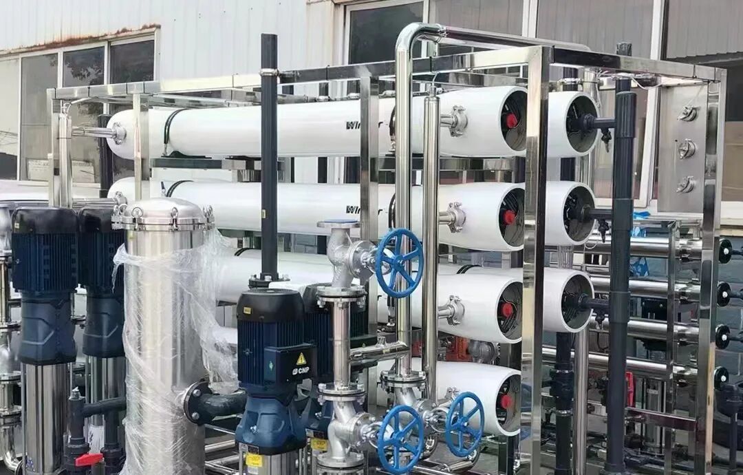
Master these nine critical limit parameters and implement proper daily maintenance to effectively extend the service life of membrane elements.
Three Critical Pressure Limits (Red Lines)
1. Maximum Feed Pressure
The maximum allowable feed pressure for standard brackish water RO membranes is approximately 41 bar; standard seawater RO membranes range from 69 to 83 bar, while high-pressure concentrate membranes can withstand pressures up to 120 bar.
Instant overpressure will tear the glued seams of membrane envelopes or rupture pressure vessels. Long-term mild overpressure compresses the membrane support layer, resulting in permanent permeate flow loss that cannot be restored by cleaning.
⚠️ Water hammer shock causes far greater damage than steady-state overpressure. Avoid sudden pressure surges during system startup, shutdown and valve adjustment.
2. Maximum Differential Pressure of Single Membrane Element
For standard 8-inch spiral-wound RO membranes, the differential pressure across a single element shall not exceed 1.0 bar.
Excess differential pressure leads to axial sliding between membrane envelopes and feed spacers, known as the "telescope effect". Once the membrane envelopes are damaged, the conductivity of produced water will rise sharply. Low water temperature, excessive flow rate and accumulated contaminants will all drive up differential pressure.
???? Note: This value refers to the differential pressure of an individual element, not the total differential pressure of the entire pressure vessel. Do not mix the two concepts up.
3. Permeate Backpressure Limit
The membrane can only withstand extremely low reverse pressure on the permeate side, merely 0.3–0.5 bar.
During normal operation, pressure transfers from the feed side to the permeate side to keep the membrane structure stable. If the pressure on the permeate side exceeds that on the concentrate side, the desalination layer will delaminate from the support layer, causing an abrupt, irreversible drop in salt rejection.
Common triggers of backpressure damage include emergency system shutdown, faulty valve control logic and blocked permeate pipelines.
✅ Operation Rule: Under all operating conditions, concentrate side pressure must be higher than permeate side pressure.
4. Maximum Operating Temperature
Standard aromatic polyamide membranes have a maximum continuous operating temperature of 45°C. Special thermal sanitizable membranes can withstand 60–70°C, but operation must strictly comply with the manufacturer’s temperature-pH curve.
Higher temperatures accelerate hydrolysis of the polyamide active layer and reduce salt rejection. High-temperature creep compresses the support layer, resulting in a permanent decline in permeate flow. Temperature limits must also be observed during chemical cleaning.
5. pH Tolerance Range
Conventional membranes allow a continuous operating pH range of 2–11. The range can be temporarily extended to pH 1–13 for short-duration chemical cleaning (refer to the manufacturer’s manual for specifications).
The amide bonds of polyamide are susceptible to strong acids and alkalis, which trigger acid- or alkali-catalyzed hydrolysis.
⚠️ High-risk combination: Minor pH deviation coupled with high temperature will exponentially accelerate membrane degradation. For high-pH cleaning, strictly control temperature and reagent soaking duration.
Two Types of Substances to Be Strictly Avoided
6. Free Chlorine Tolerance Limit
The free chlorine content in feed water for standard polyamide membranes must be less than 0.1 mg/L.
Free chlorine breaks the molecular chains of polyamide and causes irreversible damage to the desalination layer, leading to a continuous drop in salt rejection. Long-term exposure to low-concentration free chlorine results in chronic oxidative poisoning.
Pretreatment equipment equipped with activated carbon or sodium bisulfite shall completely remove residual chlorine from feed water.
7. Organic Solvents & Cationic Polyelectrolytes
Aromatic hydrocarbons, ketones and other organic solvents will swell and dissolve the polysulfone support layer, directly destroying the membrane structure. Excessive cationic flocculants produce irreversible electrostatic adsorption with negative charges on the membrane surface, forming stubborn chemical fouling.
Damage caused by the above two substances cannot be recovered through standard cleaning processes.
8. Feed Turbidity and SDI₁₅ Limits
Feed water turbidity shall be lower than 1.0 NTU; the maximum allowable SDI₁₅ is 5, and stable control below 3 is recommended for engineering applications.
The flow channels formed by the feed spacers of spiral-wound membranes are only 0.7–0.9 mm wide. Particulate matter is prone to accumulation, raising local differential pressure and triggering the telescope effect. High SDI values will rapidly form a filter cake layer, resulting in severe permeate flow decline that is difficult to eliminate via cleaning.
9. Maximum Feed Flow & Minimum Concentrate Flow
For standard 8-inch membrane elements:
✅ Maximum feed flow rate: 14–17 m³/h, to prevent feed spacer damage from excessive flow velocity;
✅ Minimum concentrate flow per pressure vessel: 2.4–3.6 m³/h. This maintains sufficient crossflow shear velocity on the concentrate side to flush away dissolved salts and mitigate concentration polarization and scaling.
Before adjusting the system recovery rate, first verify the minimum concentrate flow of the last-stage pressure vessel. Never pursue an excessively high recovery rate blindly.
Closing Remarks
These nine critical operational limits are summarized based on membrane material properties and extensive field engineering experience.
For daily operation and maintenance, operators must monitor four key parameters simultaneously: pressure, temperature, chemical environment and hydraulic conditions. Avoid all out-of-limit operating conditions to maximize the service life of reverse osmosis membrane elements.